
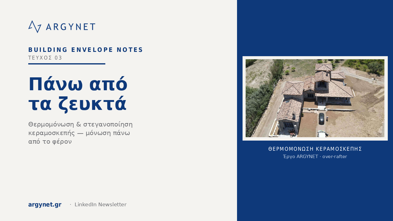
Beyond the trusses: thermal bridges, water vapour and wind pressure on a pitched tiled roof
On a pitched tiled roof, the position of the insulation is not a matter of installation detail — it is a decision that alters the very physical system of the building. When insulation is installed on top of the load-bearing structure (the slab or timber decking) rather than between the rafters, two things change radically: thermal bridges disappear by definition, and the timber remains visible from the inside. This is the German ‘Aufsparrendämmung’ method — and it is a different construction method, using different materials and with different points of failure.
This issue of Building Envelope Notes takes an in-depth look at layering. As in previous issues, the sequence of layers determined both aesthetics and fire safety; here the sequence determines three things simultaneously: the actual heat transfer coefficient, the lifespan of the timber, and whether the roof will remain in place in a strong north wind.
Why on top rather than in between
In the insulation between trusses, the timber of the beams interrupts the insulating layer. Beams typically occupy 10–15 per cent of the roof area and conduct heat by bypassing the insulation — a recurring thermal bridge that makes the effective U-value worse than the nominal one. It is calculated in accordance with EN ISO 6946 and EN ISO 10211; the bottom line is that the insulation you ‘see’ is not the insulation that ‘works’.
In insulation installed above the load-bearing structure, the layer is continuous and uninterrupted. There is no recurring thermal bridge to remove — it does not even feature in the calculation. And because the insulation extends outwards, the timber roof can remain visible from the inside: exactly what you paid for remains visible.
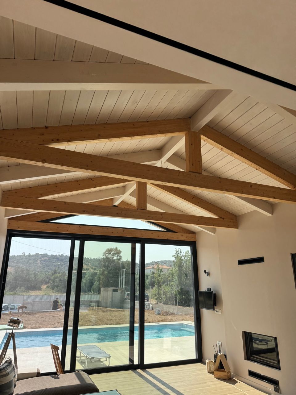
The choice is rarely purely technical. In a traditional or architectural dwelling with exposed timber, the insulation must be installed upwards — otherwise the plasterboard will conceal the characteristic feature of the space. (We analyse the reverse system, with mineral wool between the joists, as a separate solution.)
Layering, layer by layer
From the load-bearing structure outwards, the layout comprises six levels:
- Load-bearing substrate — concrete slab or timber decking, to be supplied clean, dry and level.
- Vapour control membrane on the warm side, laid on the substrate and beneath the insulation.
- Continuous-layer thermal insulation — FIBRANxps MAESTRO M boards with contact and offset joints where two layers are joined.
- A breathable membrane over the insulation, with sealed overlaps.
- Tile battens — create the ventilated cavity and support the tiles.
- Roof tiles, with air entering at the eaves and exiting at the ridge.
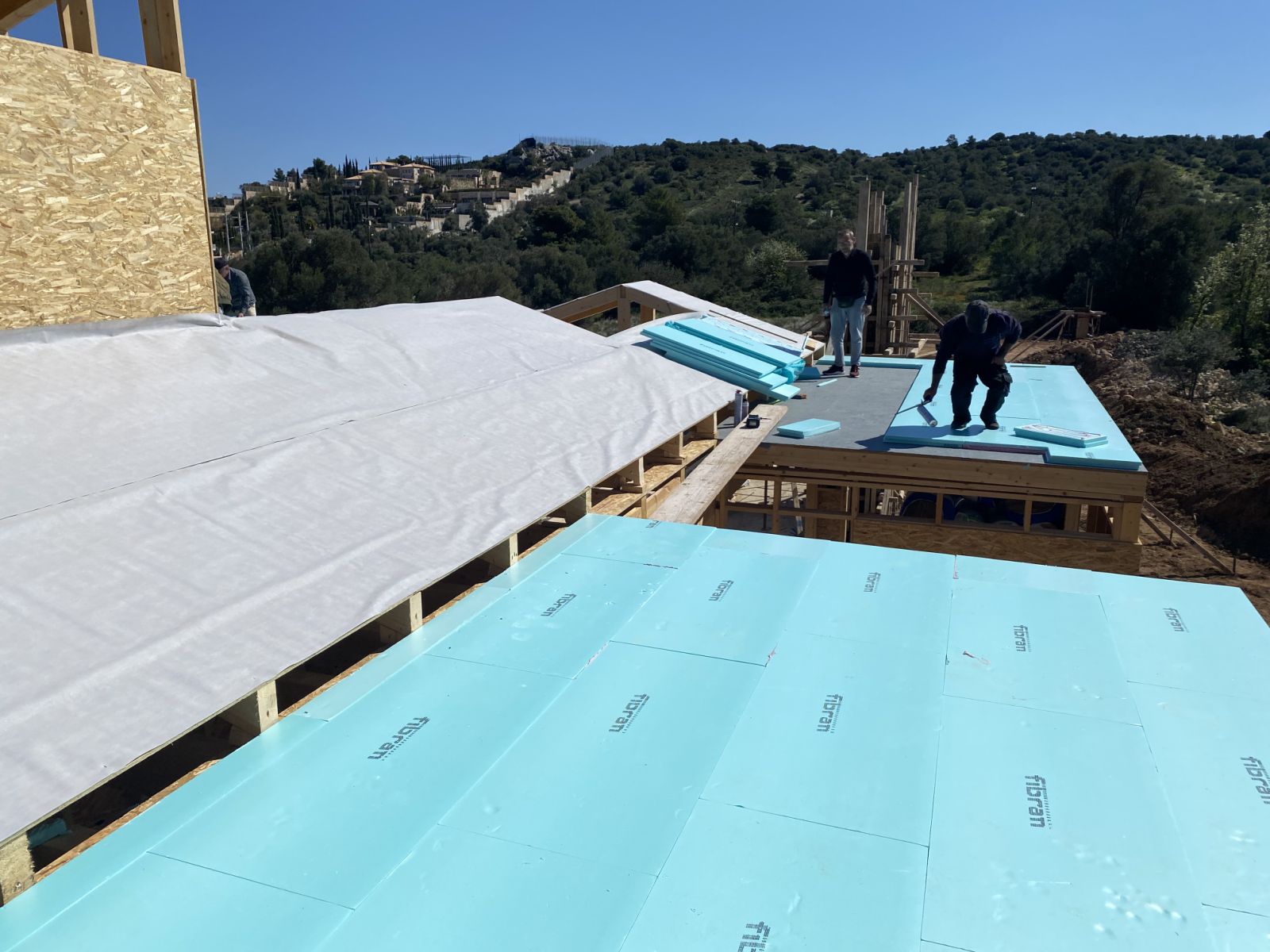
The ‘M’ profile of MAESTRO panels is not a decorative feature. It features special lugs that hold the battens in the correct position without compressing the insulation at the fixing points, and guide the fixing so that loads are transferred to the load-bearing structure. In a standard XPS panel, each fixing point causes localised compression — that is, a localised loss of thermal resistance, multiplied by the number of fixings. The ‘M’ keeps the layer continuous and uncompressed.
The physics of water vapour: why the sequence of membranes determines service life
This is where the most underestimated failure of a timber roof lies. The warm, moist air from inside diffuses outwards; if it encounters a layer cold enough for its saturation vapour pressure to fall below the local partial pressure of water vapour, the water vapour condenses within the layers — not on the surface. In a timber roof, trapped moisture leads to rot in the rafters. The risk is assessed using the Glaser method (standard EN ISO 13788); for complex or high-risk configurations, using transient hygrothermal simulation in accordance with EN 15026 (such as WUFI).
The critical factor is not the ‘quality’ of the membrane but its Sd value — the equivalent air diffusion thickness, in metres. The design principle is simple and strict: the layered structure must be more vapour-tight on the warm/internal side and more permeable on the cold/external side, so that any moisture that enters can dry outwards. For this reason, the warm side has three layers, determined by the humidity levels of the space and the margin of error:
- FIBRANskin SMART — variable Sd 8–18 m: ‘closes’ in winter, ‘opens’ in summer. It provides a summer drying path towards the interior — the ideal choice for renovation projects when you do not know what lies beneath the existing timber.
- FIBRANskin BARRIER 23 — Sd 29 m, practically airtight, 25-year guarantee: where the space generates moisture (residential properties with bathrooms or kitchens beneath the loft, hotels, healthcare buildings).
- FIBRANskin BARRIER 2400 — Sd 2400 m vapour barrier: new construction under controlled conditions.
The shortcoming of the Glaser method is also the most practical lesson: the model accounts only for diffusion, not for air transport through joints and penetrations. In reality, the moisture transported by an air current through a gap is many times greater than the diffusion through intact material. In practical terms: a vapour barrier is only as good as its worst joint. Overlaps must be sealed with special tape — simply overlapping the edges is not enough — and any hole made by a pipe, screw or electrical box must be sealed locally. And the most insidious thing of all: if fitted upside down, the same membrane traps moisture rather than preventing it.
The cold side and the Greek summer heat load
Installed over the insulation, the breathable membrane keeps out rain whilst allowing water vapour to escape. However, there is a second function that is particularly relevant to the Greek summer. FIBRANskin VENT SILVER features a reflective coating with an emissivity coefficient ε = 0.10: it reflects the infrared radiation from the heated roof tiles without impeding heat diffusion (Sd = 0.03 m). The thermal resistance of the cavity reaches 0.57 m²K/W in accordance with EN ISO 6946 — a value included in the design calculations, not a marketing claim.
In south and south-west-facing buildings, on islands and in southern Greece, or where the loft is inhabited directly beneath the roof, the reflective variant helps to reduce the summer heat load — that is, the problem which thermal insulation alone can only partially address. On a north-facing building or a shaded roof, simple breathable insulation is sufficient.
And the ventilated cavity is not optional: it removes moisture, reduces the summer heat load by drawing heat away before it reaches the insulation, and dries the membrane after rain. It requires an inlet at the eaves and an outlet at the ridge, fitted with protective screens. A cavity that is blocked at one end does not ventilate; it becomes a chamber of stagnant air.
The crucial factor: fixing, not insulation
Above the trusses, the bolts pass through the entire thickness of the insulation and must be adequately anchored to the load-bearing structure. Their length, diameter and pitch are not determined empirically — they are derived from wind pressure calculations in accordance with Eurocode EN 1991-1-4: wind zone, building height, pitch and position on the roof. The perimeter zones and corners are subject to much greater uplift than the centre and require more frequent fixing.
This is where cost-cutting takes place, and this is where the project fails. The roof does not come away gradually — it comes away all at once. And it is not just the insulation that comes away: the battens, the membrane and the tiles come away with it.
Fire protection: when to use XPS, when to use stone wool
XPS is an organic, and therefore combustible, material. Where fire protection is critical — and as we saw in the previous issue, in high-risk areas the reaction to fire determines the outcome in the first few minutes — the same installation above the load-bearing structure can be carried out using non-combustible Class A1 stone wool (FIBRANgeo B-001) instead of XPS. This represents a trade-off between thermal performance and fire reaction, and the decision rests with the design team.
Design series
The correct sequence of decisions for a roof of this type:
- Type of substrate (concrete or timber formwork) — determines fixings and any bituminous sub-base.
- New build or refurbishment — specifies a fixed vapour barrier or a ‘smart’ membrane with a variable Sd value.
- Calculation of wind pressure — length, diameter and pitch of screws per roof zone.
- Insulation thickness for the climate zone — without any allowance for thermal bridges, as there are none.
- Fire protection requirement — if critical, use stone wool instead of XPS.
- Ventilation — louvre height, inlet and outlet, fly screens.
The conclusion
Insulation above the trusses is not ‘the same insulation in a different position’. It is a different hygrothermal regime, where the sequence of layers determines three things simultaneously: the actual U-value (no thermal bridges), the lifespan of the timber (moisture can dry outwards), and whether the roof will remain in place (fastening). At ARGYNET, we specify the entire layering system and calculate materials and fixings per m².
The complete technical guide, including all products and specifications, is available in the ARGYNET LAB solution. If you are designing or constructing a pitched tiled roof with exposed timber, send me the project details. We will provide the full build-up, fixing calculations and material requirements per m².
— Dimitris Argyriou, ARGYNET
Sources & bibliography
- EN ISO 13788 — Hygrometric and thermal performance of building elements; assessment of the risk of surface and internal condensation (Glaser method).
- EN 15026 — Transient hygrothermal simulation of building elements (e.g. WUFI).
- EN ISO 6946 — Thermal resistance and thermal transmittance; calculation, including air gaps.
- EN ISO 10211 / EN ISO 14683 — Thermal bridges in structural elements; calculation.
- EN 1991-1-4 (Eurocode 1) — Wind actions; suction in roof zones.
- FIBRAN & ESHA Technical Data Sheets (TDS) for the products listed.
Technical news sent to your email
New technical solutions, articles and applications from ARGYNET LAB.