
How is the dimpled drainage membrane installed in the foundations?
Last updated:
The dimpled drainage membrane does not provide waterproofing — it protects the waterproofing. Cones facing the wall, a filter where the backfill consists of fin
The system at a glance
- DRAIN E 400 | Dimpled drainage membrane
- DANODREN H15 PLUS | HDPE dimpled drainage membrane with geotextile
- MAXISTUD GEO | 20mm HDPE dimpled drainage membrane with geotextile
- GEODRAIN PLUS | Drainage pipe with geotextile
- SNW Superior | Thermally Treated Filtration Geotextile
- NW Standard | Non-woven polypropylene geotextile
- ESHAHYDROBENT | Water-swelling bentonite cord - waterstop
Solutions & Applications · Drainage
The dimpled drainage membrane does not provide waterproofing — it protects the waterproofing and relieves pressure. It is this distinction that determines everything: if the wall has not been properly waterproofed, no dimpled drainage membrane will save it; if it has, the dimpled drainage membrane is what will keep the waterproofing intact for decades.
The two functions
| Function | What it does | Why it matters |
|---|---|---|
| Mechanical protection | Protects the waterproofing layer from stones and pressure during backfilling | Waterproofing rarely fails on its own — it is damaged during backfilling |
| Relief of hydrostatic pressure | It directs water vertically towards the base, rather than allowing it to accumulate on the wall | A water column implies pressure; without pressure, even a small defect will not leak |
Surface preparation
Before installation, the wall must already have been waterproofed — using bituminous emulsion, a brush-on cementitious compound or bituminous membrane. The waterproofing must be delivered dry and continuous; the dimpled drainage membrane does not cover any gaps, but conceals them.
The point where failure usually occurs is not the wall surface but the construction joint between the plinth and the wall. It is there that water finds a path which no external coating can seal off. This is addressed during the concreting process, using a water-swelling bentonite cord which expands when exposed to moisture and seals the joint from the inside.
Orientation: the crucial point
The most frequently asked question on a building site: which way round do you put the ‘eggs’?
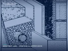
The projections face towards the wall. This creates an air gap between the wall and the membrane, through which moisture can drain and the surface can be ventilated. The smooth side faces the ground and bears the pressure of the backfill, without the grains becoming lodged between the projections.
Reverse installation is not merely less effective: the gap fills with soil, the drainage channel ceases to exist and the membrane becomes nothing more than a simple sheet of nylon laid on top of the waterproofing.
The gap you create is also the point where blockages can occur. A plain HDPE membrane, without a filter, allows the fine particles of the backfill to be carried by the water into the channel. There, they settle, gradually filling it up and eventually reaching the drainage pipe, which they also block.
Failure is silent and slow: the basement does not start leaking in the first winter, but in the fifth. And by then, rectifying the problem means excavating all the way round the perimeter to the full depth of the building.
The solution is a composite membrane with a pre-bonded geotextile filter, or the installation of a geotextile between the membrane and the backfill. At ARGYNET, we specify the system according to the particle size distribution of the backfill and calculate materials per running metre.
Installation steps
- Unrolling: the roll is unrolled horizontally along the length of the wall. The top edge is positioned at least 15 cm above the level of the future backfill and is cut off at the end.
- Overlap: at joints, either lengthways or heightways, by at least 15 cm. The projections of one sheet ‘interlock’ with those of the other, so as to maintain the continuity of the channel.
- Fixing: this is carried out at the top, above the waterproofing line, using special nails and plastic washers that distribute the pressure. No drilling below the water level.
- Foundation base: the membrane is ‘turned up’ to cover the drainage pipe, which is surrounded by gravel and geotextile.
- Finishing profile: a plastic or metal profile is fitted at the top edge to prevent soil and leaves from entering the gap.
- Backfilling: in layers, without large stones in direct contact and without machinery pressing directly against the membrane.
The fifth step is often referred to as optional. It is not: without a finish, the gap acts as a funnel that collects debris from the surface and directs it precisely where it should not go.
The pipe must lead somewhere
The dimpled drainage membrane carries the water down to the base. From there onwards, if there is no organised drainage system, the water simply accumulates at the foot of the foundation — that is, at the point of greatest hydrostatic pressure in the entire structure.
- Perforated pipe with a filter at the base, sloping towards a collection point.
- Manholes at the corners — a network that cannot be inspected cannot be maintained.
- Discharge into an absorption well, a stormwater drain or a natural receiving body, depending on the water level and the relevant planning permission.
- Cover with gravel and geotextile to prevent the pipe from becoming blocked by fine particles.
Why DRAIN E 400
- Mechanical protection of the waterproofing: resistance to static load >20 kg (EN 12730), to impact >20 mm (EN 12691) and resistance to tearing by a nail >300 N (EN 12310-1) — it accommodates the gravel and rubble of the backfill instead of the membrane.
- Open channel: 5 mm high cones, air volume >5 litres/m² and flow rate 250 litres/min·m — continuous ventilation of the wall and pressure relief.
- Soil resistance: resistant to soil chemicals and bacterial attack; resistant to root penetration and non-biodegradable. Certified to EN 13967.
The DRAIN E 400 does not have a filter. Where the backfill contains fine-grained material, a membrane with a pre-bonded geotextile should be selected — DANODREN H15 PLUS or MAXISTUD GEO — or a filtration geotextile is installed on the soil side.
Summary of materials
| Material | Role |
|---|---|
| Dimpled drainage membrane | Waterproofing protection & vertical drainage |
| Geotextile filter | Prevents the channel from becoming blocked by fine-grained material |
| Nails with plastic washers | Fixing above the waterproofing line |
| Finishing profiles | Sealing the gap at the top edge |
| Perforated pipe & gravel | Drainage of water away from the site |
| Water-swelling cord | Sealing of the footing-wall joint during concreting |
Design series
- Water table: this determines whether the project involves the management of seepage water or permanent hydrostatic pressure — two entirely different types of project.
- Grade analysis of backfill: this determines whether a composite membrane with a filter is required.
- Wall depth and height: these determine the height of the water column and the required compressive strength.
- Drainage route: where the water ends up — this is planned before the membrane is selected.
- Concrete joints: a waterstop must be incorporated during the reinforcement stage, not afterwards.
- Backfilling programme: layers, materials and equipment — this is where the system fails.
Foundation drainage
Filter, Protection & Joint Sealing
Related Solutions from ARGYNET LAB
Does the drainage channel have a filter — or will it fill with soil?
Request a Technical Quotation