
Technical Guide to Flat Roof Thermal Insulation and Waterproofing (with existing water drainage slopes)
Last updated:
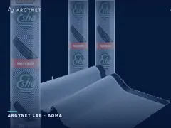
In blind waterproofing, trapped air causes blisters to form. ESHAPERFO vapour pressure release layer, heat-sealed onto XPS and anchored.
The system at a glance
- ESHACOAT 6S | Elastomeric bituminous emulsion
- FIBRANxps 300 | Flat roofs
- CERESIT CT 84 | Low-expansion polyurethane foam
- FIBRANxps INCLINE | Creating slopes
- ESHASTICK TUB | Self-adhesive waterproofing tapes
- VANDEX UNIMORTAR 1 | Waterproofing and repair mortar
- ESHAPERFO | Perforated bituminous membrane for a vapour pressure release layer
- ESHADIEN ULTRAWHITE SBS -20 | Cool roof
- ESHADIEN SBS -20 | Elastomeric bituminous membrane
- ESHAFIN SBS -10 | Elastomeric bituminous membrane
- ESHAGUM APP -10 | Polymer-modified bituminous membrane
- ESHASEALER No1 | Asphalt joint sealant
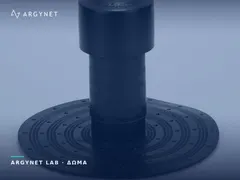
- Flat Roof Vent
Solutions & Applications · Specialised Bituminous Membranes
The conventional flat roof system comprising a vapour barrier, XPS and bituminous waterproofing has a hidden weak point: any moisture trapped between the insulation and the membrane has nowhere to go. This system provides an escape route — and this is what ensures its longevity.
When is this system suitable?
The title contains the condition: existing drainage slopes. The slab already has its own gradients — at least 1.5–2 per cent towards the drains — and the XPS slabs are laid directly on top, following this gradient. No cement screed is required for the slopes, so there is no need for the accompanying one-month curing period.
| Slab condition | Field of specialisation |
|---|---|
| Correct gradients, ≥ 1.5–2 per cent | This system — XPS applied directly to the slab |
| Inadequate or non-existent gradients | Solutions using insulation (XPS of variable thickness) or mortar prior to insulation |
| Requirement for a smooth, visible finished surface | Polyurea liquid-applied membrane system |
| The durability of the waterproofing is a priority | Inverted roof |
Step 1 — Preparation & vapour barrier
The surface must be cleaned of dust, oil and loose material. ESHACOAT 6S is applied in two cross-coated layers and acts as a vapour barrier: it prevents indoor water vapour from reaching the insulation and condensing within it.
This position is not arbitrary. The vapour barrier is always installed on the warm side — on top of the slab, beneath the insulation.
Step 2 — Thermal insulation layer
FIBRANxps 300-L panels are installed with ‘L’-shaped edges, which eliminate the linear thermal bridge at the joint. They are bonded using Ceresit CT 84 low-expansion polyurethane foam — around the perimeter of each panel and in a strip down the centre — and are bonded together at the joints using the same foam, resulting in a continuous layer without gaps.
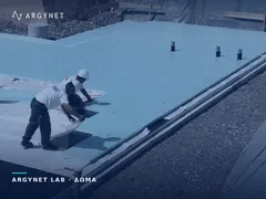
The flame is directed only at the roll — never at the substrate. During heat-welding, the blowtorch is directed at the underside of the bituminous membrane as it is unrolled. The molten bitumen passes through the holes in the ESHAPERFO and adheres at specific points to both the perforated layer and the XPS underneath.
The softening of the XPS surface at these points is slight and to be expected — this is how the bond is formed. However, it becomes a problem when the flame remains or is directed towards the substrate: XPS softens at temperatures much lower than that of the blowtorch, and the polyurethane foam in the joints is flammable.
This is why the work requires an experienced contractor crew and a controlled pace, with particular attention paid to joints, edges and penetrations, where the XPS is most exposed. Locally melted XPS beneath the membrane is not visible upon completion — it later manifests as a thermal bridge or a depression. At ARGYNET, we specify the entire layering process in accordance with the manufacturer’s instructions.
Step 3 — Parapets & gutters
Prior to the main waterproofing, a curved channel is formed at the junction of the flat roof and parapet using repair mortar, to ensure a smooth transition for the membrane. ESHASTICK TUB self-adhesive tape is applied to the corner as an additional elastic layer — this is where the greatest stresses from thermal expansion and contraction occur.
Step 4 — Waterproofing & ventilation: the key to the system
In a ‘blind’ double waterproofing system, where the bituminous membrane is bonded across the entire surface, any air or moisture trapped underneath expands in the sun and causes the membrane to blister. Over time, the blisters turn into cracks and the cracks into leaks.
- Vapour pressure release layer: the perforated ESHAPERFO membrane is laid loosely, without being bonded.
- Primary waterproofing: the elastomeric bituminous membrane is heat-welded and spot-bonded, solely through the holes in the perforated layer. A continuous network of air channels remains between the bonding points.
- Overlaps: at least 10 cm along the length and 15 cm at the joints, with firm pressure applied so that bitumen oozes out at the edge — visible proof that the seam has been bonded.
- Flat roof vents: these connect to the channels in the perforated layer and allow water vapour to escape into the atmosphere. They are installed in the upper sections of the roof slope, where warm, moist air accumulates.
Without vents, the vapour pressure release layer has nowhere to escape — the ducts are there, but they are blocked. This is the most common area where cost-cutting takes place, and it negates the entire rationale of the system.
What flexibility for the top layer?
The system’s membrane remains exposed. The choice of flexibility is determined by this condition:
| Condition | Membrane |
|---|---|
| A protective layer will follow — slabs, gravel | ESHAFIN SBS −10 °C |
| Exposed top layer | ESHADIEN SBS −20 °C — greater resilience to ageing |
| Exposed, with the aim of reducing the summer heat load | ESHADIEN ULTRAWHITE SBS −20 °C — reflective cool roof surface |
The flexibility temperature is not related to the coldness of the region — it is an indicator of the amount of elastomer in the mixture, that is, how many temperature cycles the membrane will withstand before hardening. On an exposed Greek flat roof, there are hundreds of such cycles per year.
Step 5 — Perimeter mechanical anchoring
The wind passing over the flat roof creates negative pressure — it pulls the membrane upwards. The greatest stress is concentrated at the perimeter and in the corners, precisely where delamination begins.
- Upstand: the membrane must extend up the parapet by at least 20 cm.
- Fixing: aluminium or galvanised strip at the top edge, screwed in place every 20–30 cm.
- Sealing: the upper edge of the strip is sealed with ESHASEALER No. 1 joint sealant to prevent water from penetrating behind the membrane.
A lift that starts at the parapet does not remain localised: the wind gets under the membrane and lifts it like a sail. The flashing costs very little compared to the flat roof it protects.
Case studies: 2,000 m² flat roof at the IDER premises
The system was implemented on an industrial-scale basis at the IDER premises in Agios Stefanos, Attica, in collaboration with ESHA’s technical department. Prior to the intervention, the building suffered from water ingress in offices and storerooms, as well as high energy costs for heating and cooling. The thermal insulation and waterproofing addressed both issues.
| Layer | Material on site |
|---|---|
| Vapour barrier | ESHACOAT |
| Thermal insulation | XPS 7 cm |
| Slopes | Lightweight concrete — the slab did not have sufficient reinforcement |
| Vapour pressure release layer | ESHAPERFO with flat roof vents |
| Top coat | ESHADIEN ULTRAWHITE SBS −20 — cool roof |
| Parapets | ESHAGUM APP −10 |
Two aspects of the project confirm the points outlined in this guide. Firstly, the slab did not have the required gradients, so the drains were installed before the system was completed — the second row of the ‘when it is suitable’ table. Secondly, the final membrane remains exposed, which is why the white reflective −20 °C membrane was chosen rather than the −10 °C one: lower thermal stress, lower summer heat load and a surface suitable for the future installation of photovoltaic panels.
Design series
- Checking gradients: using water or a spirit level. If these are insufficient, the system must be amended before materials are purchased.
- Condition of the slab: damp, spongy areas, cracks.
- Insulation thickness for the climate zone.
- Top-coat test report: determines the flexibility of the membrane.
- Number and positions of vents based on the surface area and geometry of the flat roof.
- Perimeter details: flashings, formwork, anchoring, guttering, penetrations.
Vapour Barrier & Thermal Insulation
Details & Ventilation
Main Waterproofing & Anchoring
Case studies & Related Solutions
Are there any vents — or does the vapour pressure release layer have nowhere to breathe?
Request a Technical Quotation